Make every 3v3 device rechargeable
Electronics
This is a circuit that was design to charge a 3.7 V lipo battery and, if is necessary, act as a power supply, in both cases the the output voltage is 3.3 V.
Download the files here!
The Circuit and How It Works
For this design I wanted to address these requirements:
- Charge a 3.7 V Li-Ion/Li-Po Battery at maximum 4.2 V through USB.
- Be able to use a device with the circuit while it's recharging the battery.
- The circuit must have an output of 3.3 V.
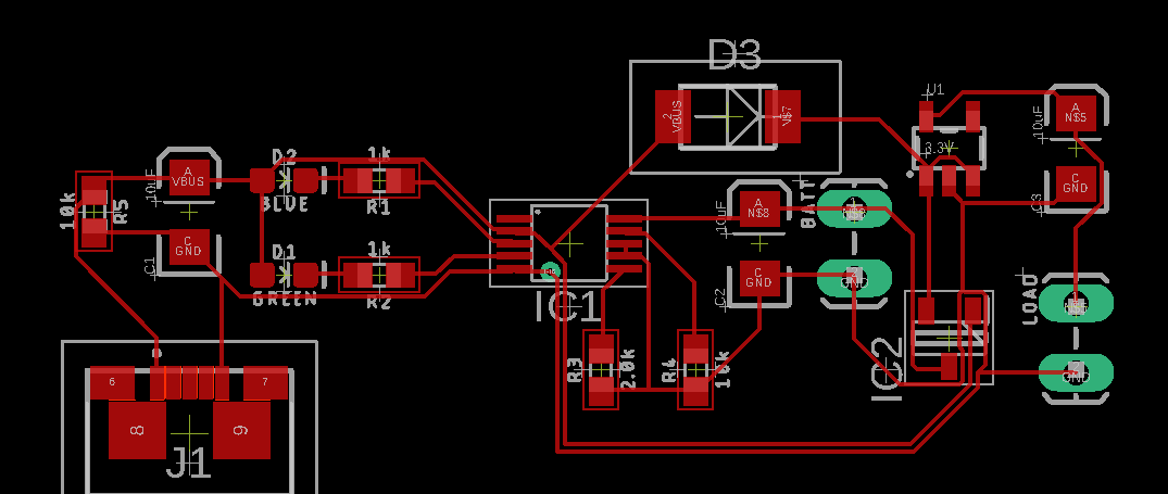
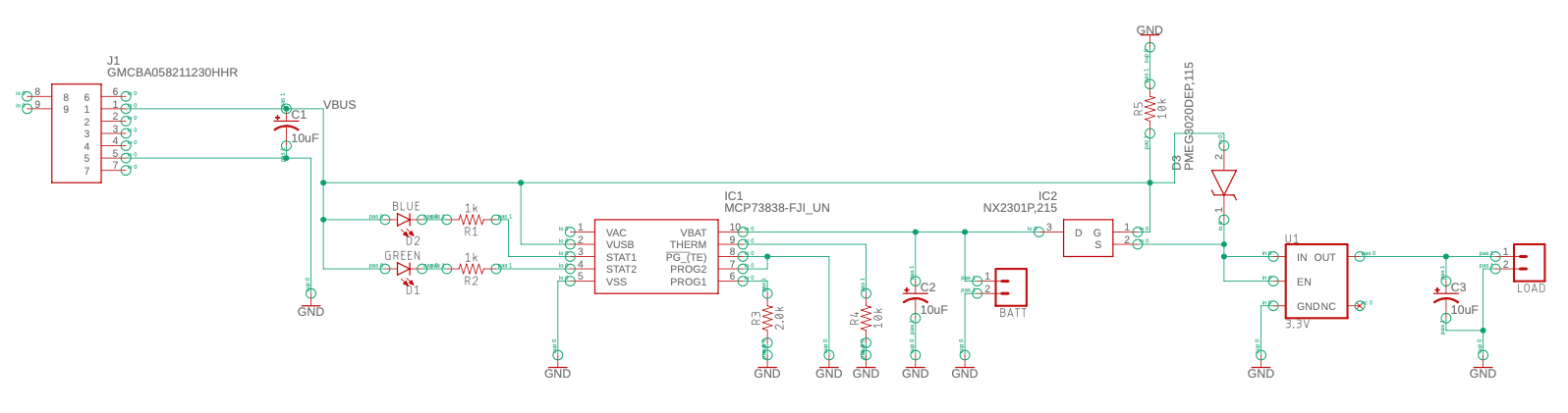
This is the final scheme of the circuit:
The heart of the design is the MCP73838, this IC is a battery charge management controller, it requires a few elements to work, the typical application (available in the datasheet) circuit is:
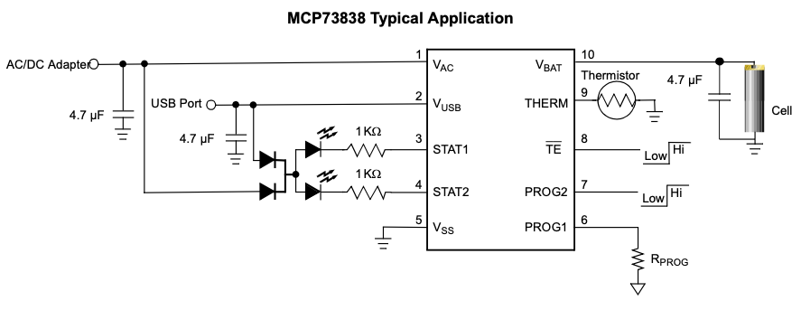
As my intention is charge through USB I just ignored all the AC configuration like the double diode with common cathode and the Vc connection, pin 3 and 4 indicates the actual state of the charging process and faults:
| Mode | STAT 1 (Pin 3) | STAT 2 (pin2) |
| Standby | High Resistance | HighResistance |
| Precondition | LOW | High Resistance |
| Fast Charge | LOW | High Resistance |
| Charge Complete | High Resistance | LOW |
| Temperature Fault | High Resistance | High Resistance |
As you can see, the information provided by the LEDs can be misunderstood, like standby and temperature fault, but it's easy to see what state it really is because standby occurs when you haven't connected the battery. In my design, the STAT2 pin is connected to a green LED, and the STAT1 LED is connected to a blue LED (why not red? I don't remember, I'm still wondering).
The TE pin is set to low to activate the built-in safety timer of four, six, or eight hours (depending on the model) that puts the charge IC in standby. The ROG2 pin is also set to low because the AC functionalities are not used. PROG1 is connected to a resistance to set the current that is supplied to the battery. In this case, a value of 2K ohms was selected to provide 500 mA (recommended 0.5C of the battery). The equation used is equation 4.1 available in the datasheet:
IREG = 1000V/RPROG
The other part of the circuit is intended to be a load-sharing system (more detailed information is available in the application note; some pictures presented are from it). The VBUS (voltage supply from the USB) must supply the load when it's present. If not, the battery energizes the load:
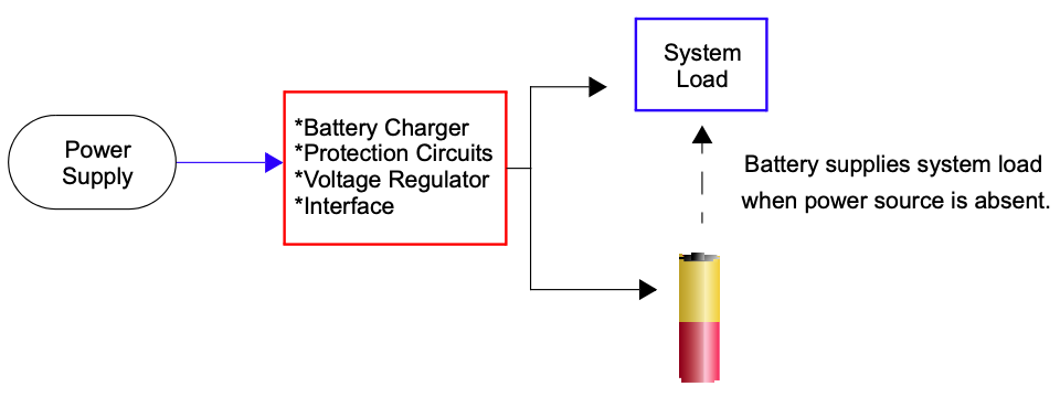
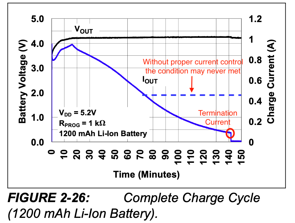
It is important to follow the schematic in the image above because if you connect the load directly to the battery, a very important issue appears. The battery charger can become confused and keep recharging the battery even if it is already fully charged. This is dangerous. This phenomenon happens because the MCP73838 automatically ends the charging process at a specific current value.
So a PMOS circuit based is designed to avoid any current issues:
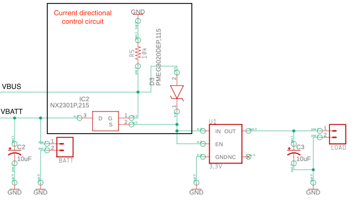
The PMOS gate is set to 0V through a pull-down resistor (R5). This ensures that the MOS turns on when VBUS is absent. In this situation, the battery energizes the load. Due to the fact that the transistor is not ideal, it has a maximum dropout voltage of 1.1V (typically 750mV). This is one of my major issues because in the worst-case scenario, the maximum voltage supply for the 3.3V regulator is 3.6V (and typically 3.95V), but in practice, I have never noticed it. In the example log, the device works just well for a week or more until it gets discharged. Continuing with the circuit, if the VBUS is at 5V (maximum 6V due to the IC battery management system specifications), the PMOS gets turned off, and the load is energized by the USB supply. The diode has a forward voltage of a maximum of 520mV, so the voltage on the IN pin of the 3.3V regulator is 4.48V. It really doesn't matter because it is a constant voltage. Another factor that this diode is useful for is to avoid a current flow from the source to the gate or from VBATT to VBUS. Nevertheless, there is still a leakage of 50uA (worst-case scenario), which generates a voltage across R5 of 500mV. It's a safe value because it doesn't turn off the MOS. Finally, the 3.3V regulator has a maximum dropout voltage of 400mV, so the input must be above 3.7V (typically, it is 250mV, which implies a Vin of 3.55V). The biggest allowed current is 600mA, so keep that in mind if you want to use it.
Use Example: Inexpensive 2.4MHz Mouse Converted to Rechargeable
As an example, a cheap wireless mouse is used. The idea is to replace the AAA batteries with a rechargeable one. I didn't find the datasheet of the IC in the mouse, but since it uses 3V, I assumed a Vin of 3.3V would be just fine. So, I simply tore apart the battery holder and placed the circuit with the new battery in that space.
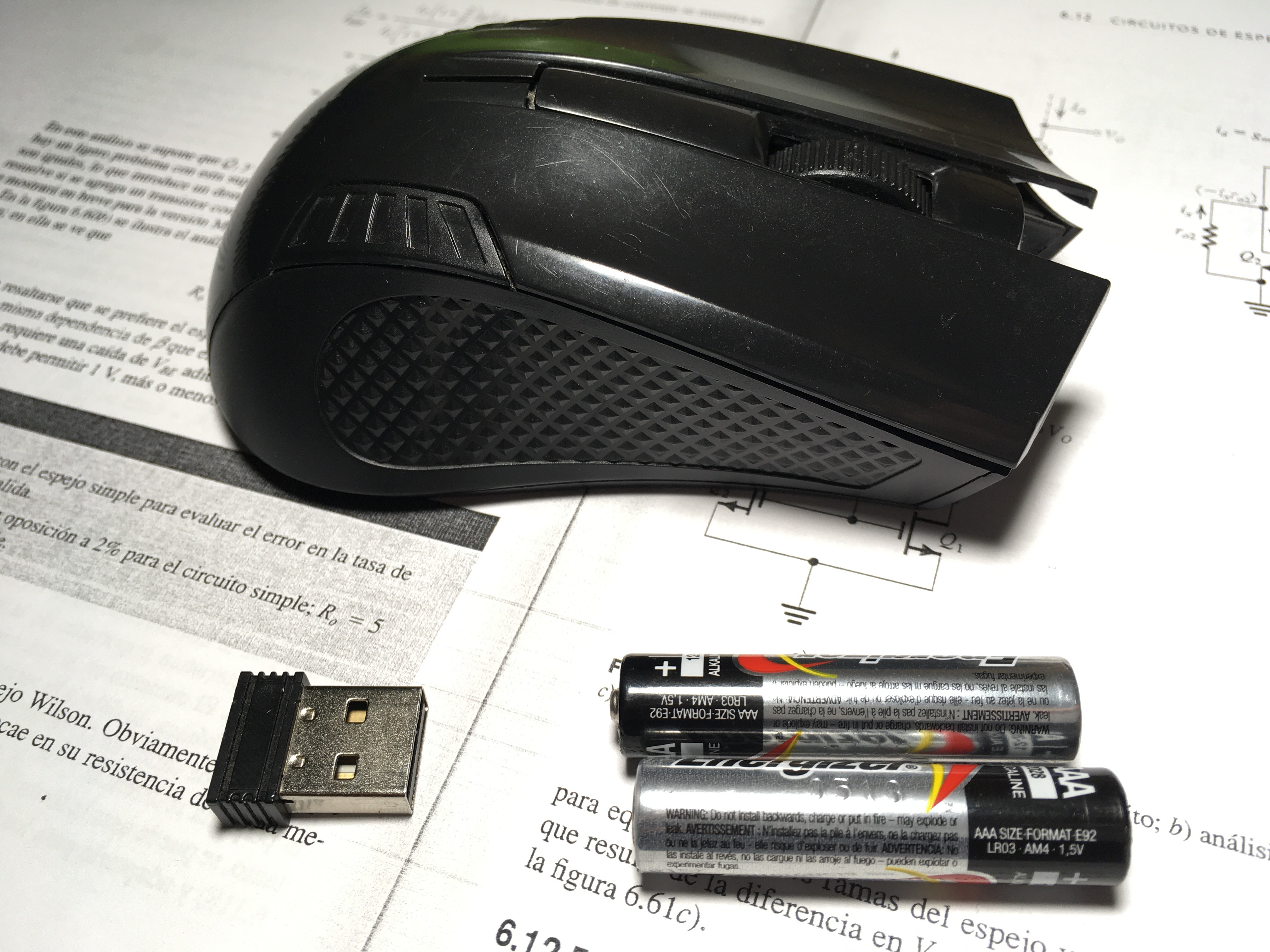
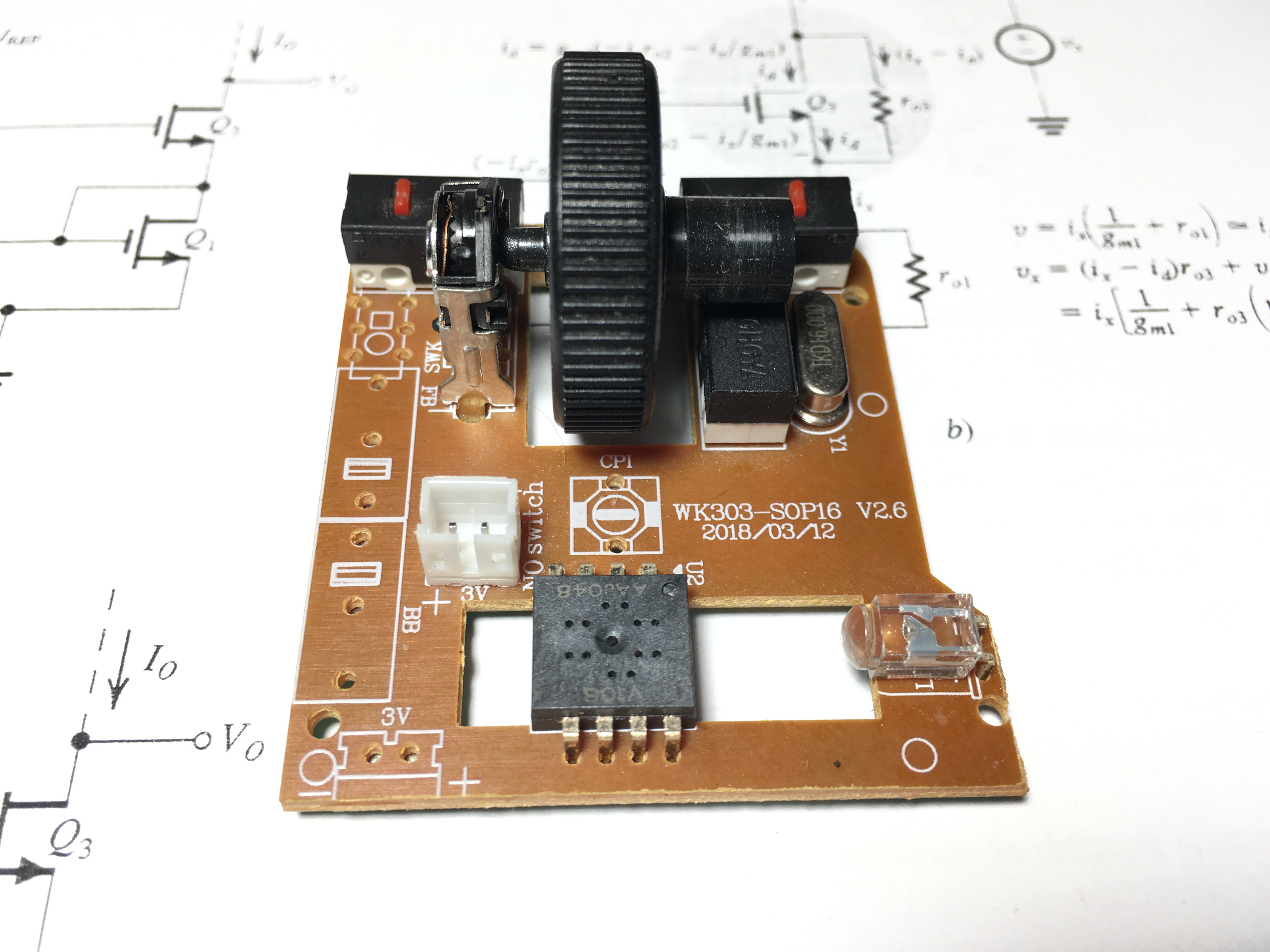
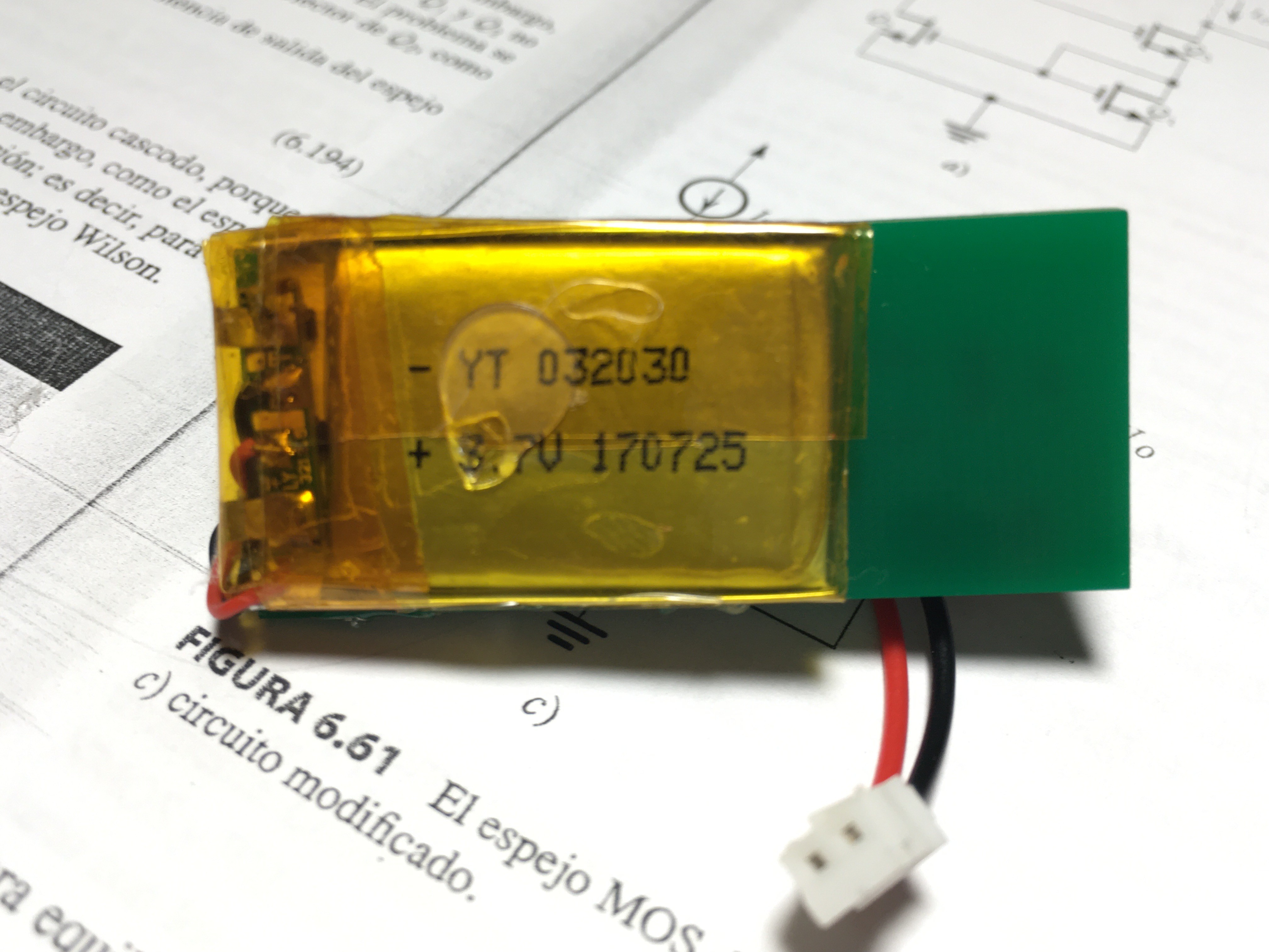
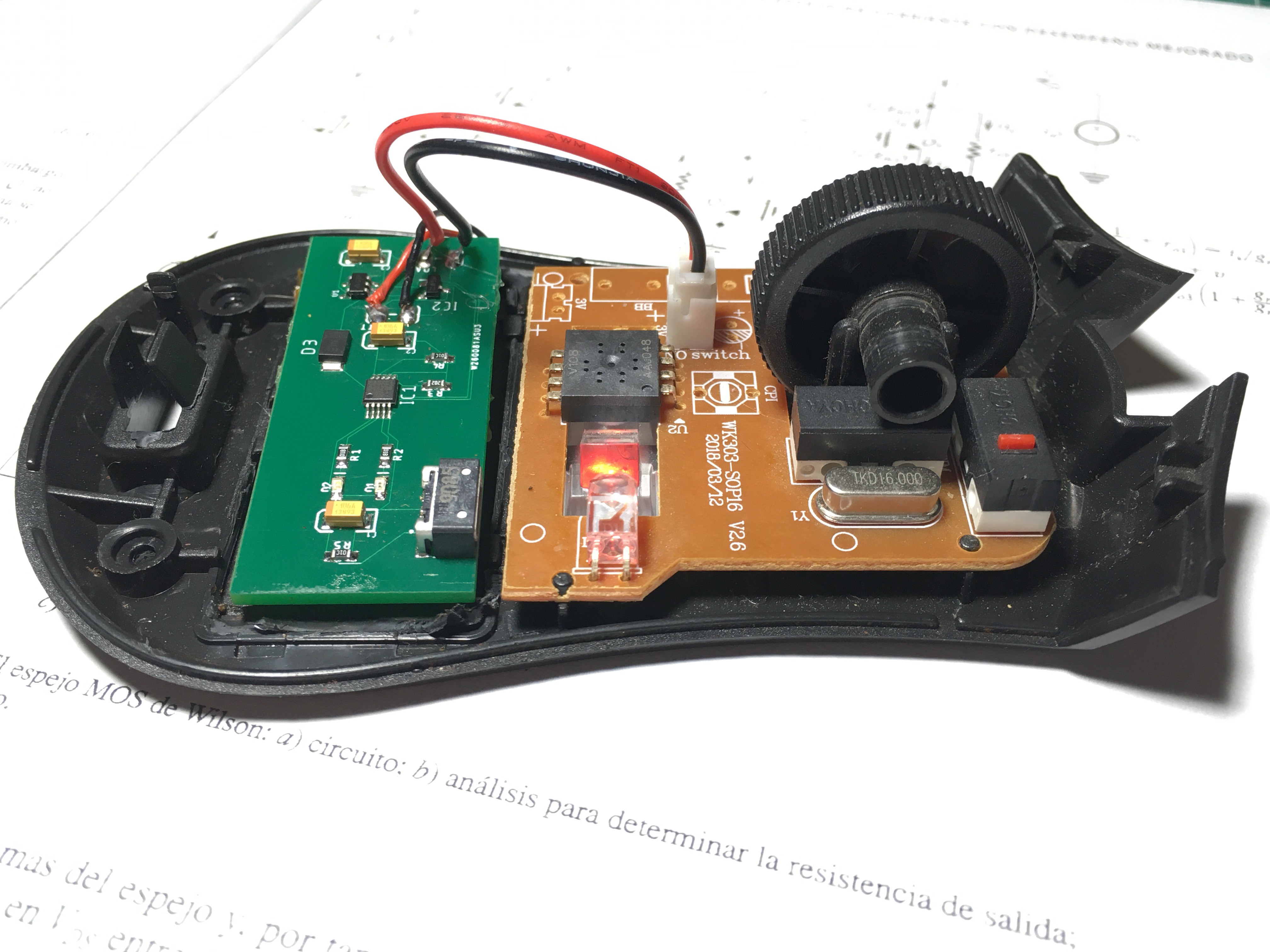
The mouse consumes 25 mA at 3.0V, and the battery can provide 250 mAh. Ideally, with this setup, the mouse can be used for approximately 10 hours on a single charge. To enhance the design, the mouse case can be modified for easier access to the USB charger port. For this modification, a 3D-printed case would be recommended. Creating a custom-designed case would allow for a seamless integration of the charging port while maintaining the mouse's ergonomics and aesthetics.
While the initial conversion demonstrates the feasibility of converting a disposable battery device into a rechargeable one, further refinements through case modifications can significantly improve the user experience and overall functionality of the rechargeable wireless mouse. However, for the purposes of this example, the demonstration concludes with the successful integration of the rechargeable battery and charging circuit into the existing mouse case.